
Description
Overview
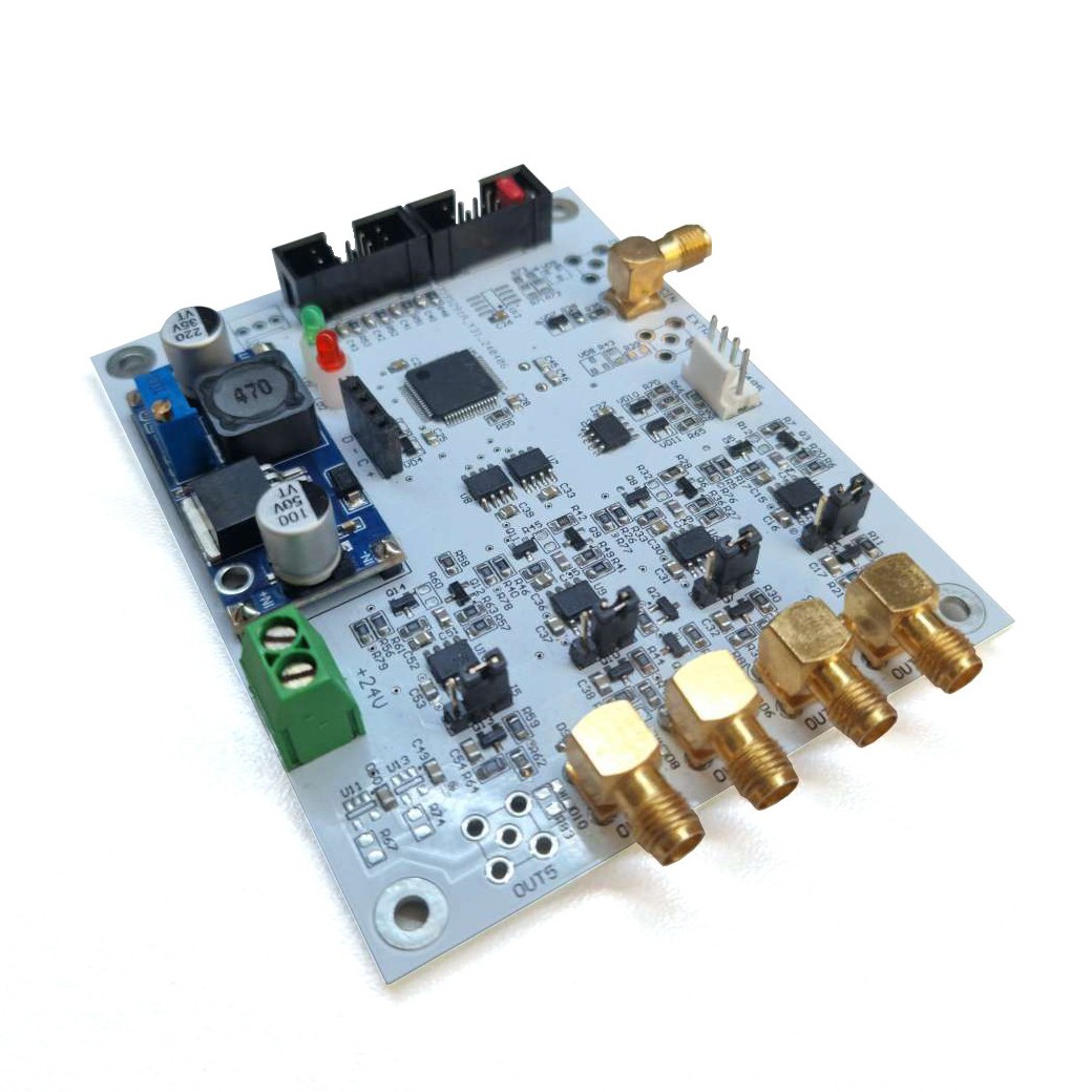
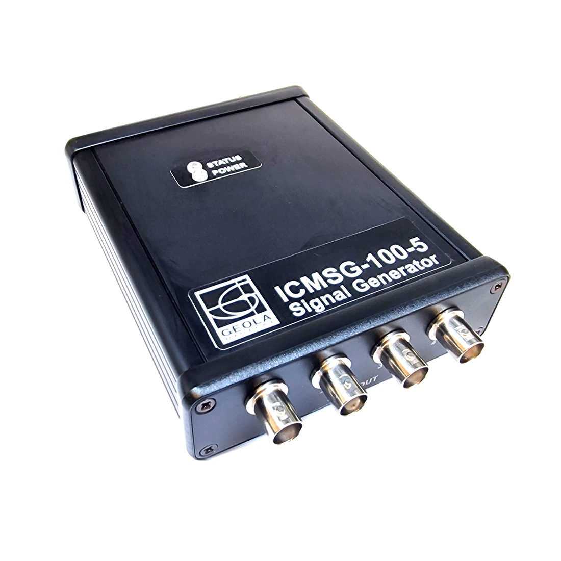
The ICMSG-100-5 Digital Pulse/Delay generator is a four-channel device designed for synchronizing various equipment, with its primary application in scientific and technological industry (for example – laser photonics).
Key features
1. Frequency Range:
- The ICMSG-100-5 Digital Pulse/Delay generator operates within a frequency range of 1 Hz to 100 Hz.
2. Output Signal:
- The output signal is a 5V CMOS waveform (with a possible range of 5V to 20V upon request).
- It exhibits high noise immunity and has a jitter of less than 1 ns.
3. Compact Design and Low Power Consumption:
- The ICMSG-100-5 Digital Pulse/Delay generator boasts small dimensions and consumes approximately 150 mA of power from 24V DC.
- Its compact form factor makes it suitable for various applications.
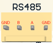
4. RS485 Interface:
- The Digital Pulse/Delay generator features a convenient RS-485 interface for communication.
- An RS-485 USB Type B converter is available upon request.
5. Individual Channel Configuration:
- The standout feature of the ICMSG-100-5 Digital Pulse/Delay generator is the ability to independently configure each of its four channels.
Note that there’s a version called CCMSG-100-5 without individual channel configuration, where all channels operate at the same frequency.
User-Controlled Parameters
Users can manage the following parameters:
1. Frequency:
- Set the frequency within the range of 1 Hz to 100 Hz.
2. Channel Activation/Deactivation:
- Enable or disable each channel individually without affecting others.
3. Individual Pulse Delay and Duration:
- Configure individual pulse delays and durations (up to 900 microseconds with a 1-microsecond step).
4. Operating Modes for Each Channel:
- Internal Generation Mode:
– The channel generates signals at a specified overall frequency.
- External Trigger Mode (5V Trigger or Software):
– The channel waits for an external trigger and emits a synchronized pulse at the set frequency.
– Users can define a prohibition time (1 to 10,000 seconds) after triggering, during which the channel remains blocked.
– Other channels can continue operating during inhibition time.
– Individual (software) and global triggers (5V external signal or software) are available.
- Signal Division Mode:
– Channels can generate signals with skips, emitting only every nth signal (n ranging from 2 to 65,000).
– This allows achieving virtually any divided frequency on a specific channel.
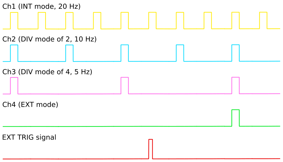
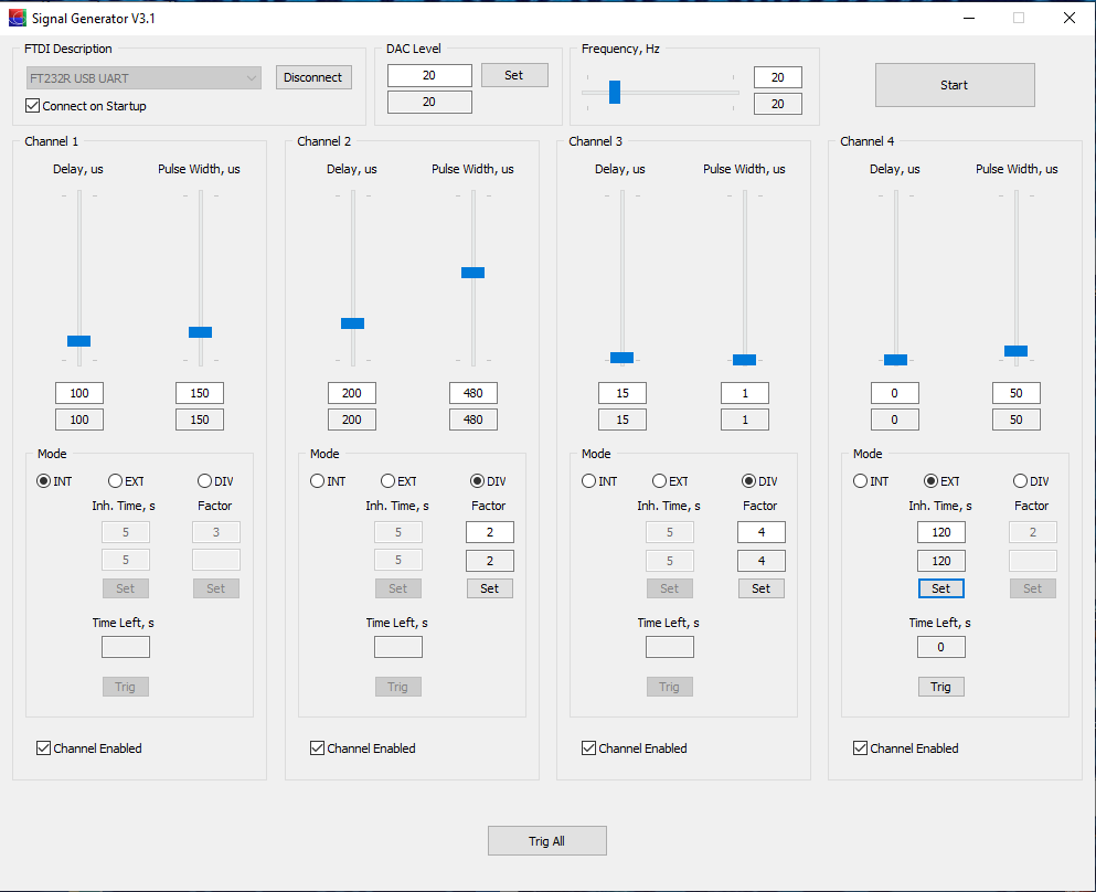
Example Scenario
1. Set the overall frequency to 20 Hz.
2. Configure the channels as follows:
- Channel 1: Internal generation mode (20 Hz)
- Channel 2: Division by 2 (10 Hz, skipping every second signal)
- Channel 3: Division by 4 (5 Hz, emitting every fourth signal)
- Channel 4: External trigger mode (waits for an external trigger, shots synchronized with other channels)
Remember that each channel retains its individual delays and pulse durations.
Specifications
| ICMSG-100-5 Model | CCMSG-100-5 Model | |
|---|---|---|
| Power source | 24 V DC | |
| Current | ~150 mA | |
| Frequency* | 1 to 100 Hz | |
| Frequency resolution | 1 Hz | |
| Pulse width | 1 to 900 µs | |
| Pulse width resolution | 1 µs | |
| Pulse delay | 1 to 900 µs | |
| Pulse delay resolution | 1 µs | |
| Number of channels | 4 | |
| Output signal type | CMOS (TTL compatible) | |
| Output level | 5 V (5-20 V upon request) | |
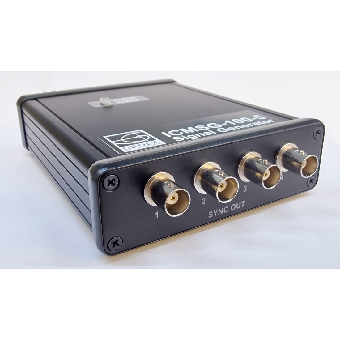
| Output connector | SMA (BNC in option with case) | |
| Signal jitter | ≤ 1 ns | |
| Channel modes | Each channel individually: INT; DIV (2 to 65000); EXT with inhibit time option, external 5 V signal or from software | INT or EXT modes only, EXT by external trig signal |
| Interface | RS-485 (RS-485 to USB adapter available upon request or with case option) | |
| Additional functions | Interlock connector (NC), physical start button, state indicator LED, user GUI software | |
* Other repetition rates can be available upon request.
Technical Details
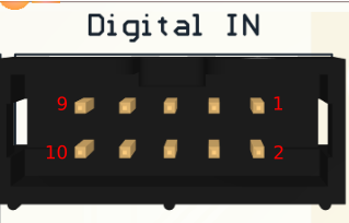
| Pin | Function |
|---|---|
| 1, 3, 5, 7, 9 | GND |
| 2 | Interlock (+3.3 V pull up) |
| 4 | Start button illumination (+3.3 V when generator is started, 0 V – stopped) |
| 6 | Start button input |
| 8 | External state indicator LED |
| 10 | Reserved |