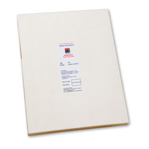
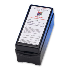
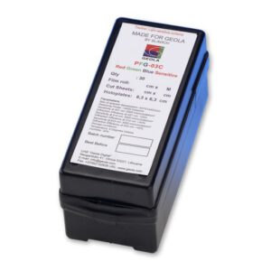
Along other light sensitive materials supplied for various markets, Geola Digital is glad to offer self-processing Color Photopolymer Bayfol® HX 200 film in two shapes, rolls and sheets.
Bayfol® HX 200 is a light-sensitive, self-developing photopolymer film which can be used to produce phase holograms in the form of volume reflection and volume transmission holograms.
Bayfol® HX 200 can be recorded with appropriate laser light within the visible spectral wavelength range from 440 nm to 680 nm. For hologram formation no further post-treatment is necessary, e.g. neither a wet nor a thermal treatment.
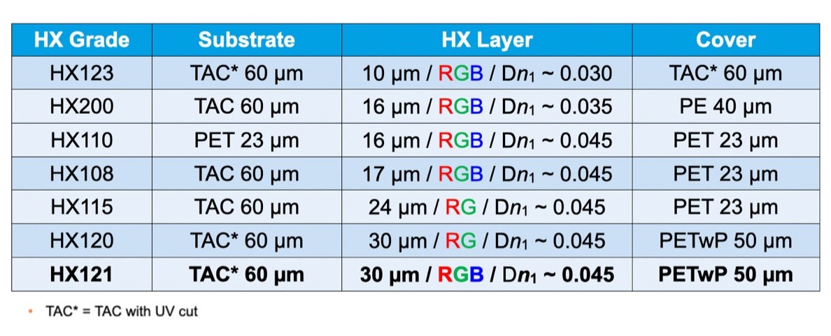
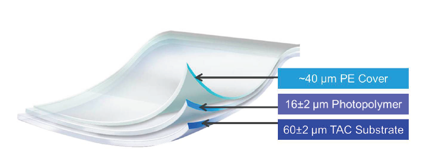
Bayfol® HX 200 consists of a three layer stack of a substrate, a light-sensitive photopolymer and a protective cover film. The substrate is a cellulose triacetate film (TAC), and the protective cover is a polyethylene film (PE). The protective cover film can be removed from the photopolymer.
The product is capable of being used for a variety of types of volume holograms.
Please find the Bayfol® HX 200 standard sizes available from Geola Digital.
Layer stack, schematic
Approximate laser pulse dosage:
λ = 633 nm
approx. 15 mJ/cm²
λ = 532 nm
approx. 20 mJ/cm²
λ = 457 nm
approx. 25 mJ/cm²
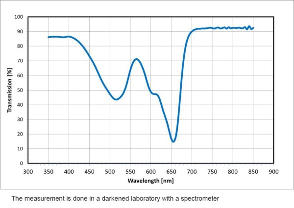
Transmissions spectrum of the unrecorded photopolymer film
Guideline data1)
General properties
Property
Value
Unit of measurement
Method
Typical substrate thickness
60 ± 2
microns
acc. to ISO 4593, 23°C
Typical photopolymer thickness
16 ± 2
microns
white light
interferometer
Typical cover layer thickness
40
microns
acc. to ISO 4593, 23°C
Density with cover foil
1.15
g/cm3
ISO 1183, 20°C,
Method C
Optical properties
Transmittance (unrecorded film, w/o cover foil)
See spectrum
above
%
ASTM E 01348
Haze (after UV flood cure2))
< 2
%
ASTM D 1003
Index of refraction nD of the substrate
1.485
Prism coupler
Index of refraction nD of the
photopolymer (unrecorded)
1.500
Prism coupler
Index of refraction nD of the
photopolymer (after UV flood cure2))
Maximum refractive index modulation Δn1 per recording wavelength λ
ISO 17901-2
λ = 633 nm
> 0.03
λ = 532 nm
> 0.03
λ = 457 nm
> 0.03
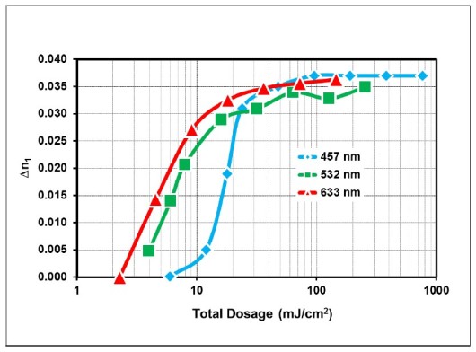
Typical recording dosage needed to achieve above Δn1 values
ISO 17901-2
λ = 633 nm
˜ 15
mJ/cm2
Applied total dosage
λ = 532 nm
˜ 20
mJ/cm2
Applied total dosage
λ = 457 nm
˜ 25
mJ/cm2
Applied total dosage
Shrinkage and spectral shift
Effective thickness shrinkage
(after recording and UV flood cure2))
˜ 1.4
%
Reflection holograms
Spectral shift (after recording and UV flood cure2))
˜ -8
nm
Denisyuk holograms:
Wavelength deviation
between recording and
reconstruction
1) All values provide general information and are not part of the product specification.
2) Curing is done by means of a Mercury lamp; Company: Hönle; Typ: MH-Strahler UV-400 H); dosage about 5,000-10,000 mJ/cm².
3) Holographic method: Denisyuk holograms Reflection holograms are recorded in a Denisyuk setup with an expanded plane-wave laser beam. The backside object is a plane mirror. Schematic figures of the setup are provided in the appendix.
4) Holographic method: Reflection holograms ISO 17901-2 method to measure the amplitude of refractive index modulation using the reflection hologram, using two expanded plane-wave laser beams. Typical total power density: 9-23 mW/cm². The beams are s-polarized. External angles of incidence are -22° (object beam) and +42° (reference beam) in air, tilted to normal direction. Dosage curves and schematic figures of the setup are provided in the appendix.
General information for flood cure and bleaching
Example: Conditions for mercury lamps
Photopolymer layer on substrate laminated to glass
Dosage: 5,000-10,000 mJ/cm²
Intensity at the sample: 40 mW/cm²
Given cure and bleaching exposition parameters are just recommendations and should serve as guidelines.
High temperatures (above 60°C at the film) should be avoided because they can lead to deformation of the substrate.
General handling instructions
The product is light sensitive. Exposure to light prior to the holographic exposure might sacrifice the refractive index modulation Δn1 and diffraction efficiency η. Exposure can be calculated using our Online Exposure Calculator. Examples for tolerable expositions in dark room environment (dim yellow light) without sacrificing the holographic performance are given below:
Property
Value
Unit of measurement
Method
Maximum exposure intensity
2.6 1)
µW/cm²
Photopolymer film Laminated, positioned at 30cm distance
0.8 2)
µW/cm²
Maximum exposure time
5 1)
min
30 2)
min
1) Illuminant: OSRAM PARATHOM DECO CLASSIC A Yellow 1 Watt LED E27
2) Illuminant: PHILIPS AccentColor Miniglobe Yellow 1 Watt LED E27
Storage conditions
The unrecorded photopolymer film should be stored in the original and sealed container that is used for delivery, whenever possible. Storage temperature shall be kept at >15°C and <25°C and humidity level (RH) of around 40-60%.
While the recorded film is quite stable, the unrecorded photopolymer film should be protected from light, humidity, heat and foreign materials.
Safety
While there are no specific toxic threats, photopolymer film is a trial product that has not yet been fully tested. As such, safety precautions should be taken during its handling and use. Precautions should be taken to avoid direct contact of the unrecorded photopolymer with skin – gloves or other suitable personal protection devices should be used.
Determination of the holographic performance
To determine the holographic performance of Bayfol® HX 200 film, the following samples were prepared: Under dark room conditions first the protective cover film was removed from cut pieces of Bayfol® HX 200 film. Then these pieces were laminated with their photopolymer surface onto glass slides (75 mm x 50 mm x 1 mm) or onto a plane mirror. To facilitate optical contact between the photopolymer layer and the glass surface or mirror surface pressure was applied with a soft roller.
The samples which were prepared as described above were holographically recorded either in a Denisyuk setup, a 2-beam reflection hologram setup in plane-wave geometry.
After the holographic recording and a waiting time of at least 10 seconds the samples were flood cured and bleached with a UV lamp (see above). The performance of the holograms was then determined according to the respective recording geometry with the methods described below.
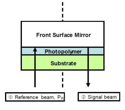
Denisyuk holograms (plane-wave to plane wave)
In this recording geometry the photopolymer film is laminated onto a plane front surface mirror.
The recording is done with a normal incident collimated laser beam (plane wave). The recording dosage is given by the incident laser power density PR times the exposure time.
Recording of Denisyuk holograms
λ = 532 nm
λ, nm
PR, mW/cm2
532
4.6
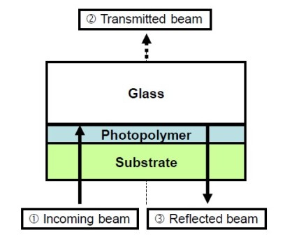
Readout of Denisyuk holograms
Transmission and reflection spectrometer
Evaluation of λreconst. „On Bragg“ condition
Evaluation of Tmin „On Bragg“ (2)
Evaluation of Rmax „On Bragg“ (3)
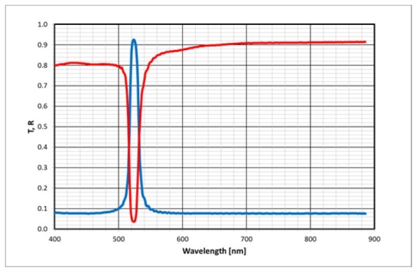
To determine the performance of the hologram, the recorded film sample is re-laminated on a glass plate. Then the transmission spectrum and the reflection spectrum through the hologram at normal incidence are measured with a spectrometer (steag etaoptik, ETA-RT).
From these spectra the above listed performance parameters Tmin, Rmax, spectral bandwidth (FWHM) and the spectral shift (λreconst. – λ) can be extracted. An example of such spectra is shown in the following figure.
2-Beam reflection holograms (plane-wave to plane-wave)
In this recording geometry the photopolymer film is laminated onto a glass plate (75 mm x 50 mm x 1 mm).
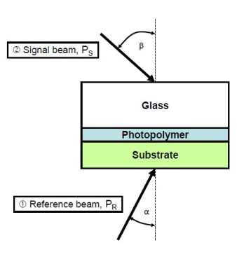
The holographic recording is done with two coherent and collimated laser beams (plane waves), which penetrate the prepared sample from its two different surfaces. Both laser beams have S-polarization to maximize the interference contrast (fringe visibility) of the holographic recording.
The holographic recording itself is done with dosages which correspond to the product of the total incident power density (PR + PS) multiplied by the individual exposure times, t. More detailed conditions are depicted in the two following figures.
The ratio (PS / PR) = 1.29 compensates for the different size of the projected beam cross sections onto the sample surfaces and the different losses due to Fresnel reflections at the air sample interfaces in such a way that inside the photopolymer layer the beam ratio is equal to 1. This again facilitates maximum fringe visibility during the holographic recording.
Recording of slanted reflection holograms
λ = 633 nm, 532 nm, 457 nm
S-Polarization
λ, nm
α, °
β, °
PR, mW/cm2
PS/PR
633
-22
42
4
1.29
532
-22
42
7
1.29
457
-22
42
10.5
1.29
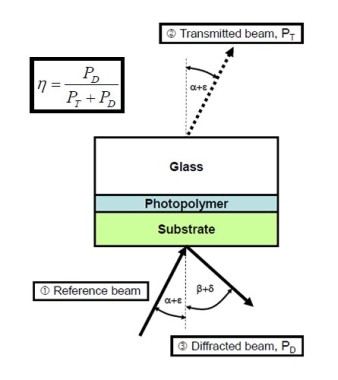
Readout of slanted reflection holograms
λ = 633 nm, 532 nm, 457 nm
S-Polarization
Adjust ε and δ for maximum diffraction efficiency η
λ, nm
α, °
β, °
633
-22
42
532
-22
42
457
-22
42
To determine the performance of the hologram, the diffraction efficiency η of the recorded hologram is measured with respect to the rotation angle α (the holographic film / glass sandwich is mounted on a rotation stage). The resulting Bragg curve η(α) is analyzed according to the Kogelnik theory*, to deduce the above listed performance parameters ηmax, Δn1 and the effective thickness shrinkage. The effective thickness shrinkage is obtained from the angular shift ε, which measures the deviation from the recording angle α to the angle at which ηmax is achieved. This thickness shrinkage is incorporated in the fit of Δn1 according to Kogelnik theory.
By varying the recording times the dosage response curves for Δn1 at the different recording wavelengths, λ = 633 nm, 532 nm and 457 nm, can be obtained.
General references to the holographic performance
Bayfol® HX 200 is a light-sensitive, self-processing photopolymer film in which the recording process is based on monomer diffusion caused by the inhomogeneous photopolymerization during holographic exposure. Therefore, the refractive index modulation Δn1 will in general be dependent on the grating spacing of the recording interference field as generated by the respective holographic recording setup.
Since the grating spacing of transmission holograms is larger than that of reflection holograms, the achievable refractive index modulation Δn1 is smaller for transmission holograms than for reflection holograms recorded at comparable total power densities. The refractive index modulation Δn1 for transmission holograms can be increased at a fixed dosage by using lower power densities PR and PS at the cost of a longer exposure time t.
The photopolymerization in Bayfol® HX 200 film is a free-radical photopolymerization and can be inhibited by oxygen that is, for example, dissolved in the photopolymer layer. Therefore a significant refractive index modulation Δn1 can be detected only above a specific, minimum dosage. This inhibition dosage is needed to consume all oxygen that was originally dissolved in the photopolymer layer. This inhibition dosage can be overcome also by using a suitable incoherent pre-exposure.
At significantly smaller power densities PR + PS and, therefore, much longer illumination times, a reduction of the refractive-index modulation Δn1 can be observed. This is due to diffusion of oxygen dissolved in the substrate or permeation of oxygen through the substrate into the photopolymer layer during the exposure time period. This additional oxygen further reduces conversion of the free radical photopolymerization which results in smaller Δn1 values.
In addition the achievable refractive-index modulation Δn1 can be influenced by the ratio (beam ratio) of the power densities of the signal beam and the reference beam in the above-mentioned recording geometries. The maximum Δn1 is obtained if this beam ratio is equal to 1 inside the photopolymer layer. The external power density ratio (PS / PR) has to be adjusted in such a way that different incident angles and different Fresnel reflection losses at the sample surfaces result in a beam ratio equal to 1 inside the photopolymer layer.